
Fabricademy: Week 2: Digital bodies

One of the projects which immediately got be hooked on doing the FabTextile course was the fact that we would be building our own mannequins. Not only this but learning how to design them. I’ve really enjoyed catching up on this weeks project! Now I have the basic structure of a mannequin that I will look forward to using in the future. If you’d like to know how I did it, just carry on reading…
Program outline
References of the representation of the human figure in art, The mannequin in haute couture, Human proportions, Measuring the body, Digital fabrication techniques : waffle/ stucking/ triangulation, radial, bending, kurf patterns, Scanning, Laser cutting, 3D printing, CNC milling, Vacuum forming, Materials, 3D Scanning, 3D Modeling.
Tools/software
-
3d scanner
-
kinect, sense3d, etc
-
3d modelling software: rhinoceros 3d & grasshopper, solidworks, fusion360, freecad, blender etc
-
makehuman
-
open fit lab open frameworks
-
laser cutter
-
big milling machine
-
vacuum forming
Materials
-
cardboard 3mm
-
hi density foam
-
wood & veneer
-
composites materials
-
resins, bio -resins -plastics, epoxy etc
-
fibers, cotton, hemp, linen, jute, etc
-
vacuum bags
Assignment
Use software to obtain a body-figure and a digital fabrication process to produce it (the production happens in groups of 3-4)
We recommend : For nodes that they need to have mannequins to exhibit their creations we suggest to create a more conventional figure that they can use.
For nodes that already have mannequins, you can experiment with different figures and forms!
How will it be evaluated?
-
document use of a 3D scanner to acquire a model
-
document repair of 3D model mesh
-
experimented with the combination of milling, laser cutting, vacuum forming and composites
-
built your own mannequin
-
include all the files in the documentation
Human body, sketches and initial research


Initially I became very interested in mannequins which can move their individual limbs and I wanted to explore the way parts of the copy tag heuer formula 1 body are separated into parts.
I looked also at wooden toys which move using elastic, historical versions of mannequins and even joint shapes.
Our project continued with the 3D Modelling program. The steps were to:
- Use MakeHuman to create a human shape, then export it as an .stl file (stereolithography). (Click Here)
- Using base measurements of our own body and then adjusting these, we can get a realistic body shape for our mannequin.
- Using Rhinoceros3D, we opened the . stl file
- With the Mesh2Nurbs command, we can create a form by also cropping the body sections and capping them to create a whol.
- Then exporting as an .stl & .obj
- This is then opened in Slicer for Fusion360 where you can create a design for assembly
- Choose a slice design type (interlocked, stacked, radial,
- Select a material like card, perspex,
- Also change the angles and number of slices.
- Create 2D assembly files as objects, which can then be laser-cut.
- An additional step of exporting these assembly files and importing these back into Rhino3D to make the best use of the sheet/material and spacing of designed pieces.
- Using the Laser cutting program (Trotec Job Control), we can send the files to “print”, (Click Here)
- selecting the material thickness and so choosing the speed and power needed to cut the material
- within the rhino file, preset layers to either cut or engrave based on their corresponding layer colour e.g.: cutting the shape but engraving the numbers)
- Finally with the pieces laser cut out, the Assembly of the mannequin can start and the form begin to take shape
- The central numbers engraved on each form correspond to the chronological order in which they are placed and connected to each other
- The smaller numbers correspond to the line placement e.g vertical piece Z1 (z -axis) fits into all pieces on the Y axis which are numbered 1, and zo on.
- I actually took a screen-grab video using QuicktimePlayer, of the assembly stages in Slicer
- Watch the video here.
Working with MakeHuman
Here I used the program to add in my measurements and create a form. Below you can see the different views of the human form once you have entered in all the measurements, skin and hair details.
In the future I would like to post a MakeHuman Tutorial and also video as my skills develop.
Editing on Rhino3D
Using Rhinoceros3D, we opened the .stl file
- With the Mesh2Nurbs command, we can create a form.
- I decided to use a box as a splitting object to help me crop the body sections.
- Afterwards used the command for capping the figure to create a whole.
- Then exporting as an .stl & .obj
- The first image below is actually a .dae file, but I have included it in the slideshow as I think it shows the form in the smoothest look. It also shows as it MakeHuman you can add and change hair designs.
Getting into Slicer Fusion 360
This is then opened in Slicer for Fusion360 where you can create a design for assembly
- Choose a slice design type (interlocked, stacked, radial, 3D, geometric)
- Select a material like cardboard or perspex
- Also change the angles and number of slices. E.g.: you can angle all the pieces to 45 degrees and have 22 slices instead of 14, or whichever number you choose.
- NOTE: sections or slices which are in red, will not work. These can be deleted or you can change angle and number of slices till the simulation you are given shows a model with only white slices.
- Create 2D assembly files as objects, which can then be laser-cut.
- An additional step of exporting these assembly files and importing these back into Rhino3D to make the best use of the sheet/material and spacing of designed pieces.
Laser Cutting the files
From Rhino3D to Trotec Job Control.
Here you can see all the pieces laid out into 8 rectangles which represent the cardboard sheets and dimensions.
- The Slicer program actually created the pieces in a laid out pattern of 13 sheets, which would have created a lot of wastage.
- So I did a post edit back in Rhino3D, just so I could re-tesselate the pieces and use less cardboard.
- I managed to reduce this down to 8 Sheets of 900x600mm cardboard.
- You can also see the details of the numbering in the images below. Again Z for vertical pieces (z axis) and Y for the horizontal.
- The last images shows all the pieces stacked up and ready to be assembled.
- I actually took a screen-grab video using QuicktimePlayer, of the assembly stages in Slicer. Watch the video here.
Assembling the mannequin
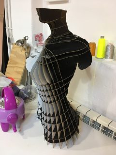
Following the numbered pieces and the engraved number slots, I began to piece the mannequin together.
As you can see, the cardboard has two colours, one side white and the other side black, which give the whole mannequin a very sophisticated look.
I chose the radial design and this you can see the most from the 2nd image.
NOTE: It is quite important to follow the numbers of the slices in chronological order, as even though I had this. I thought I had figured out the assembly steps already, putting a few pieces in too early and having to remove some already places sections to add other in.
Overall I am happy with my mannequin. It makes a nice change to see a curvier shape which is not often represented. I would however like to create a more simplified design and make another one… or two!
Some additional things I tried:
Slicer with a skeleton file : spine & skull
Recent Comments